

 ️
️
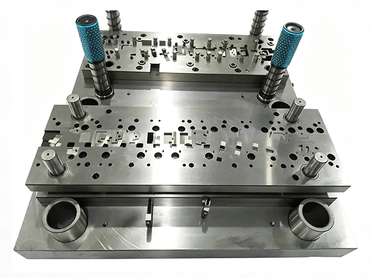
A single progressive tool integrating several precision forming operations.
The die automatically advances strip material through multiple stations to pierce, trim, bend, form, and separate ultra-thin terminals, conductive springs, connector inserts, and small structural stampings.
Typical applications include mobile and computer connectors, battery contacts, charging systems, automotive sensors, wire-harness terminals, relays, and miniature switch components.
Ultra-thin strip, springback, micro features, burr risk, die wear, and slow new-product launch.
The customer used several single-operation dies and manual transfers. Thin material and complex bends created dimensional variation, springback, and high labor cost.
- 0.05–0.3 mm strip with difficult springback control
- Several standalone dies and manual transfers
- Rapid punch and cutting-edge wear during high-speed production
- Micro holes and narrow cantilever features vulnerable to burrs and chipping
- Repeated die correction delaying new-product launch
- Batch dimensional rejection at customer incoming inspection
The customer needed one high-speed die that could control thin-strip springback, micro-feature burrs, and long-run dimensional consistency at the same time.
Primary engineering considerationWhy strip simulation, tool material, and cutting clearance determined production stability.
Thin strip stores elastic energy during bending, so forming stations required deliberate springback compensation. Waste flow and station interference also had to be resolved before steel was cut.
Micro features demanded stable guide accuracy, wear-resistant punches, and precisely controlled die clearance. Otherwise burr height and edge chipping would increase quickly during high-speed stamping.
Strip layout, springback, station interference, scrap discharge, guide accuracy, punch material, blanking clearance, heat treatment, edge wear, burr height, and maintenance access.
A simulated, wear-optimized progressive die with controlled micro-clearance.
Integrated multi-station design
Piercing, trimming, bending, forming, and separation were combined into one progressive die for continuous production.
3D strip-layout simulation
UG modeling and strip simulation were used to evaluate springback, interference, and scrap discharge before toolmaking.
Precision toolmaking
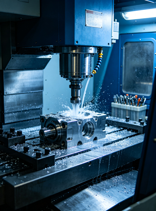
CNC machining, slow-wire WEDM, profile grinding, internal and external grinding, fitting, and guide assembly produced the critical cutting and forming geometry.
Wear-resistant materials and treatments
SKH-9 or comparable high-speed and powder steels were used for critical punches. Heat treatment, cryogenic processing, and nitriding improved wear resistance.
Micro-clearance and springback compensation
The source identifies dimensional control of ±0.003 to ±0.005 mm for critical tool features and compensation for thin-strip forming.
Production and maintenance support
High-speed trial stamping, consumable replacement, and maintenance support stabilized 24-hour production.
From strip simulation to high-speed progressive production.
DFM and strip-layout simulation
Evaluate material flow, station sequence, springback, interference, and scrap removal.
Tool-base and insert machining
CNC-machine the plates, pockets, and supporting geometry.
WEDM and profile grinding
Produce the precision cutting edges, inserts, punches, and forming features.
Heat treatment and surface enhancement
Apply hardening, tempering, cryogenic treatment, and nitriding as required.
Tool assembly and clearance fitting
Assemble guides, punches, inserts, and station components.
High-speed trial stamping
Validate strip feed, dimensions, burrs, springback, and part separation.
Production inspection and maintenance support
Monitor stamped parts and maintain wear components during volume production.
Tool and stamped-part inspection linked directly to high-speed production performance.
Critical tool features, guiding elements, punch clearance, stamped dimensions, burr condition, and springback were checked during trial and volume production.
Tool-steel identity, cutting-edge dimensions, guide alignment, blanking clearance, springback compensation, stamped-part tolerance, burr height, strip feed stability, and maintenance traceability.
Higher capacity with lower labor, burr defects, and maintenance cost.
The customer reported stable incoming quality and no rejected production lots after implementation.
The die reportedly completed million-cycle high-speed production with limited wear, while annual repair cost fell substantially.
Quantitative, certification, qualification, and environmental-test outcomes are based on the supplied project documentation and should be verified against internal records before public publication.
Long-term tooling program for electronic and battery terminals.
The customer assigned additional 3C and new-energy terminal tooling to the same development program and established an annual framework relationship.
Project outcome summary based on the supplied case record