

 ️
️
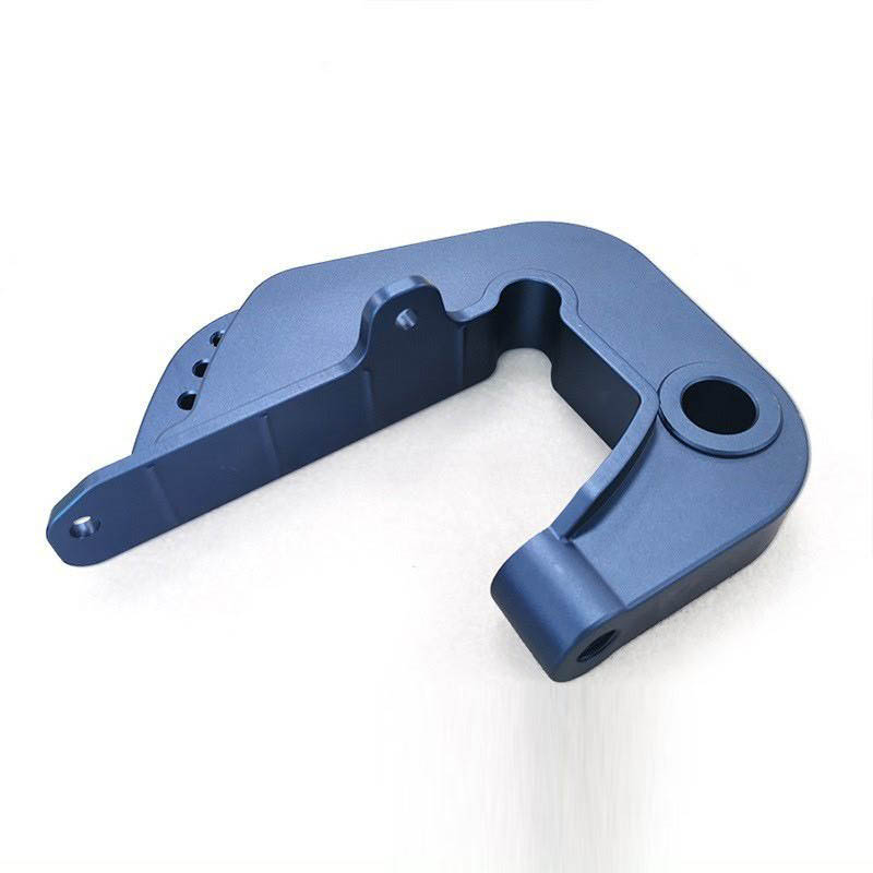
A lightweight joint arm connecting the servo drive to the moving mechanism.
The swing arm carries repeated dynamic load between a servo motor and the end mechanism. Its stiffness and bore alignment directly affect positioning accuracy and smooth motion.
Forged 6061-T6 offered a cost-effective balance of light weight, fatigue resistance, machining stability, and color-anodized appearance for medium-load automation equipment.
Bore misalignment, joint vibration, post-machining movement, and poor surface durability.
The previous three-axis process required several flips, reducing coaxiality between the mounting bores. The assembled bracket design also introduced clearance and vibration during rapid motion.
- Assembly binding caused by mounting-bore coaxiality error
- Material inconsistency in rolled plate under repeated load
- Dimensional rebound after machining without stress relief
- Vibration from a multi-piece joined structure
- Unfinished aluminum scratching and oxidizing in the workshop
- High rework and time-consuming equipment calibration
The arm needed to be light enough for servo response, but stiff and aligned enough to preserve repeat positioning during rapid repeated movement.
Primary engineering considerationWhy one-piece stiffness and bore alignment controlled equipment performance.
The two main bores established the motion axis. Misalignment created friction and binding during assembly and made servo tuning less repeatable.
A one-piece forging removed joint clearance, but roughing still released residual stress. Controlled stabilization and a smooth curved load path were required for long-term dimensional and fatigue performance.
Forging density, bore coaxiality, hole position, residual stress, one-piece rigidity, curved stress flow, servo load, anodizing thickness, and batch repeatability.
A forged one-piece arm with aligned interfaces and stabilized geometry.
Forged 6061-T6 one-piece construction
The multi-piece bracket was replaced by a dense forged aluminum component to improve fatigue resistance and rigidity.
One-setup multi-axis machining
The U-shaped profile, weight-reduction features, counterbores, and coaxial mounting bores were machined together. The source reports coaxiality controlled to ±0.003 mm.
Stress relief after roughing
Controlled vibratory aging released machining stress before finishing and reduced long-term dimensional movement.
Smooth contour finishing
Curved surfaces were machined without visible transition steps, reducing local stress concentration.
Deep-blue hard anodizing and CMM inspection
An 8–12 μm finish improved wear, corrosion resistance, and model identification. CMM inspection verified the assembly datums.
A compact manufacturing route for a stable servo-driven joint.
Forged blank preparation
Prepare the 6061-T6 forging and establish stable datums.
Multi-axis rough machining
Create the U-profile, cavities, and weight-reduction features.
Stress-relief aging
Release cutting stress before final geometry is completed.
Finish machining
Complete the coaxial bores, holes, faces, and smooth curved transitions.
Deburring
Remove sharp edges that could damage cables or seals.
Deep-blue hard anodizing
Apply the 8–12 μm protective and identifying surface.
CMM inspection
Verify coaxiality, hole position, parallelism, and batch consistency.
Inspection concentrated on the joint axis and mounting references.
The dimensional plan covered the coaxial mounting bores, positional features, end-face parallelism, anodized surface, and stability after stress relief.
Bore coaxiality, hole position, end-face parallelism, stress-relieved stability, contour smoothness, anodizing thickness and color, and lot-to-lot dimensional consistency.
Higher equipment load with lower rework and faster assembly.
The customer reported that the one-piece arm resolved vibration and binding and maintained the required repeat-positioning performance.
The lightweight structure reduced servo load, while the anodized finish remained resistant to workshop wear and corrosion.
Quantitative, certification, qualification, and environmental-test outcomes are based on the supplied project documentation and should be verified against internal records before public publication.
Annual supply program for a growing joint-component family.
Following successful production, the customer established an annual sourcing framework and continued developing additional lightweight swing-arm variants.
Project outcome summary based on the supplied case record