

 ️
️
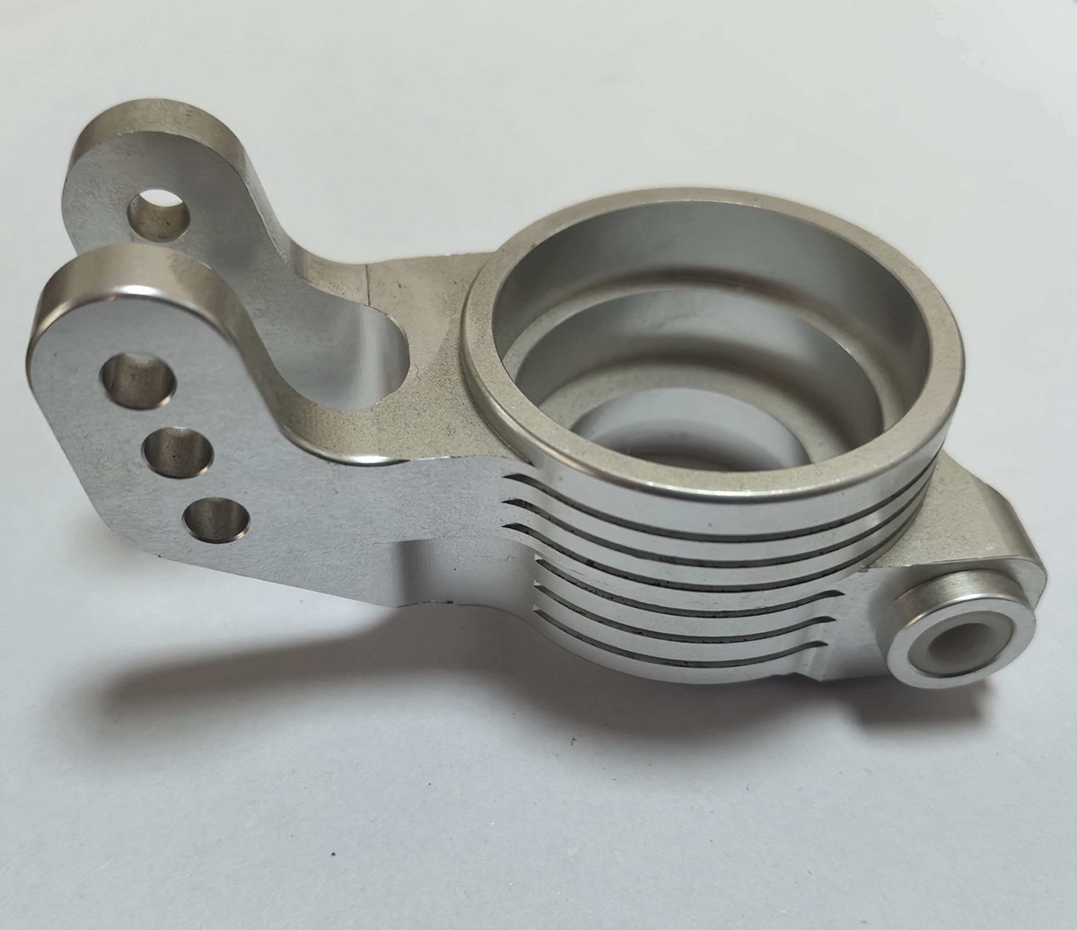
A structural bracket that also manages motor heat.
This component secures the gimbal motor while using integrated fins to dissipate heat. It is used in aerial-imaging drones, handheld stabilizers, and professional anti-vibration camera gimbals.
The part had to combine accurate motor positioning, effective heat transfer, low mass, and a refined surface suitable for a premium finished product.
Thermal instability, mounting error, thin-fin deformation, and excess weight.
The previous supplier’s part did not remove heat effectively, and the motor could become unstable at elevated temperature. Multi-sided machining across several setups also introduced mounting-hole variation that contributed to gimbal vibration.
- Insufficient heat dissipation and high-temperature motor instability
- Mounting-hole misalignment caused by repeated repositioning
- Thin fins vulnerable to vibration marks and machining deformation
- Visible tool marks inconsistent with a premium product
- Excess material reducing device endurance
The bracket had to perform as both a precision motor mount and an integrated heat sink, without adding unnecessary mass to the gimbal assembly.
Primary engineering considerationWhy thermal and dimensional performance had to be solved together.
The cooling fins could not be treated as a cosmetic feature. Their thickness, spacing, and connection to the motor-mounting body directly affected heat transfer.
At the same time, the internal cavity and mounting holes had to remain aligned. Multiple setups increased the risk of positional error, while aggressive cutting could distort the thin fins or leave visible chatter.
Heat-transfer path, mounting-hole position, thin-fin rigidity, tool vibration, overall mass, and surface consistency.
A one-piece machining route designed around stability and weight control.
Dedicated single-setup fixture
A custom fixture allowed the internal cavity, cooling fins, and mounting features to be machined in one primary setup, reducing accumulated positioning error.
High-speed layered fin machining
Controlled high-speed passes reduced cutting load on the thin fins and prevented chatter and deformation.
Optimized lightweight geometry
Material was removed from non-critical regions while maintaining the stiffness required for stable motor support.
Standardized cosmetic finishing
Fine bead blasting produced a consistent appearance, followed by cleaning and full dimensional inspection.
A controlled route for thin fins and precision mounting features.
Material preparation
Prepare the aluminum stock and establish stable reference surfaces.
Single-setup cavity machining
Machine the internal cavity and primary external geometry.
Thin-fin milling
Use layered high-speed passes to protect the cooling fins from distortion.
Hole and interface machining
Complete the motor-mounting holes and assembly features in the same setup.
Deburring and fine bead blasting
Remove sharp edges and create a uniform premium surface.
Cleaning and full inspection
Verify mounting features, overall geometry, fin condition, and appearance.
Dimensional control focused on motor alignment and fin integrity.
The inspection plan covered the mounting-hole pattern, internal cavity, assembly interfaces, fin condition, overall weight, and cosmetic consistency.
Mounting-hole position, cavity geometry, fin thickness and straightness, edge condition, surface uniformity, and production-to-production dimensional consistency.
Improved thermal control, gimbal stability, and production consistency.
The customer reported that the motor-temperature issue was resolved and that improved mounting accuracy supported more stable image capture.
The component met the target weight, supported longer device endurance, and achieved the cosmetic quality required for the customer’s higher-end product line.
Quantitative and certification-related outcomes are based on the supplied project documentation and should be verified against internal records before public publication.
A production-ready part accepted for long-term supply.
According to the supplied case record, assembly rework fell substantially, scrap remained low, and the customer approved Innova Forge as a long-term designated supplier for the component.
Project outcome summary based on the supplied case record