



 ️
️
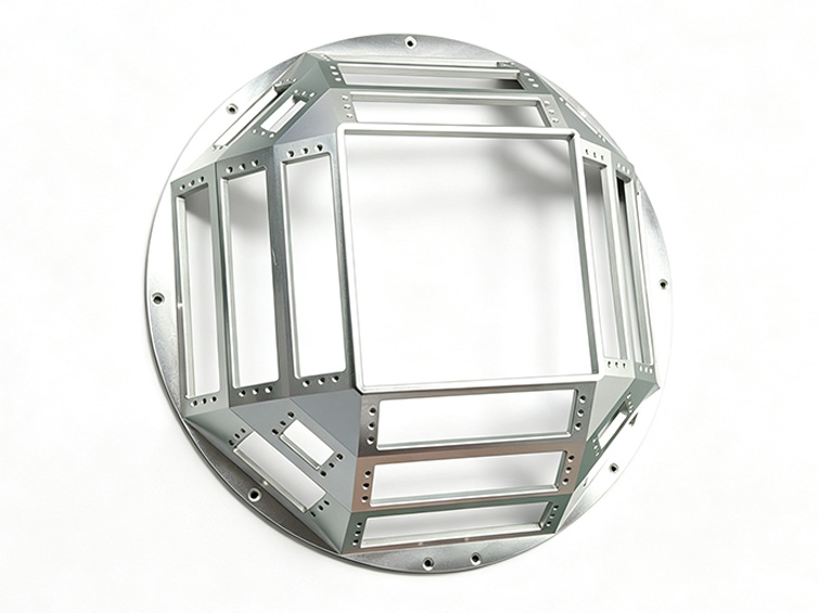
A structural platform that determines the alignment of an entire sensor array.
The mounting base supports multiple antenna elements or radar sensor modules around a circular structure, providing horizontal coverage without a major blind zone.
In addition to positioning the modules, the aluminum body can support grounding, shielding, and heat transfer for outdoor radar, communications, and monitoring systems.
Array-angle error, water ingress, insufficient rigidity, and inefficient assembly.
The customer’s earlier fabricated or sheet-metal structure relied on multiple joined sections. Angle variation between the windows affected signal consistency, while seams increased corrosion and water-ingress risk.
- Accumulated angle error across assembled array windows
- Outdoor seams vulnerable to water ingress and corrosion
- Insufficient stiffness under severe wind load
- Low mounting-hole accuracy and repeated assembly rework
- Need for compatibility with standard poles and cabinets
The base had to keep every array window aligned while remaining stiff, corrosion resistant, and easy to install in outdoor field conditions.
Primary engineering considerationWhy an assembled structure could not provide stable array geometry.
When several plates or frames are joined together, each connection introduces angular and positional variation. Those errors can affect phase consistency and the alignment of radar or antenna modules.
The large open-frame geometry also required stiffness without excessive weight. Machining strategy, residual stress, reinforcement placement, and the mounting flange therefore had to be considered together.
Window-to-window angle, residual stress, structural stiffness, wind-load deformation, hole position, outdoor corrosion, water protection, and interface compatibility.
A one-piece five-axis aluminum structure with controlled interfaces.
Stress-relieved aluminum blank
The thick aluminum stock received stress-relief aging before precision machining to reduce distortion.
Five-axis one-piece milling
The complete multi-window structure was machined from one aluminum blank, supporting an array-angle tolerance of ±0.08° in the supplied project specification.
Reinforcement and wind-load optimization
The rib structure was refined to increase stiffness while preserving the open geometry required for sensors and antenna elements.
Precision interfaces and outdoor finish
Mounting and pass-through holes were drilled and tapped under controlled datums. Hard anodizing provided a durable corrosion-resistant surface without welded seams.
Universal circular flange
The base interface was designed to connect with standard poles and cabinets without an additional adapter.
From stress-relieved plate to outdoor-ready sensor platform.
Material preparation and aging
Prepare the 6061-T6 stock and reduce residual stress before machining.
Five-axis rough and finish milling
Create the one-piece multi-window geometry and reinforcement features.
Precision drilling and tapping
Machine the mounting holes, pass-through holes, and threaded interfaces.
Edge finishing and deburring
Remove sharp edges and refine the open-frame geometry.
Hard anodizing
Add corrosion and weather resistance for outdoor deployment.
Dimensional inspection
Verify angles, hole positions, threads, flange geometry, and overall form.
Inspection centered on alignment, stiffness, and field installation.
The supplied project specification identifies an angular tolerance of ±0.08° and a mounting-hole tolerance of ±0.05 mm. Thread quality and the circular flange interface were also controlled.
Array-window angle, mounting-hole position, thread quality, flange geometry, structural reinforcement, anodized surface condition, and reported wind-load deformation.
Improved array performance and more reliable outdoor installation.
The customer reported that the finished array geometry met its alignment requirements and that field assembly and calibration became substantially faster.
The project record also reports eight months of coastal outdoor testing without corrosion or water-ingress failure.
Quantitative, certification, qualification, and environmental-test outcomes are based on the supplied project documentation and should be verified against internal records before public publication.
Repeat orders after successful outdoor testing.
The customer reported stable protection performance and reduced modification cost through the standardized flange. Additional production orders followed the initial deployment.
Project outcome summary based on the supplied case record