

 ️
️
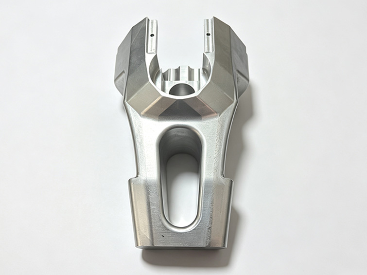
A load-bearing robot joint that combines strength, precision, and low mass.
The component forms part of the robot’s primary load-bearing structure and integrates mounting cavities for a servo motor, harmonic reducer, bearings, and sensors.
Its complex sloped faces, curved transitions, deep weight-reduction cavity, and multi-angle holes made it a strong candidate for five-axis machining from a dense aluminum forging.
Accumulated tolerance, vibration, stress movement, fatigue cracks, and long prototype cycles.
The original supplier used four three-axis setups and a multi-piece assembled structure. Datum transfer, joint clearance, and residual stress created positioning error, vibration, and inconsistent batch assembly.
- Geometric error after repeated part flipping
- Joint vibration and low load capacity from a multi-piece structure
- More than 20% rework after post-machining dimensional movement
- Visible tool transitions creating local stress concentration
- Prototype lead time exceeding 40 days
The robot needed a lighter one-piece joint with stable geometry, smooth load paths, and repeatable interfaces for high-speed continuous motion.
Primary engineering considerationWhy geometry, residual stress, and structural continuity were linked.
The multiple motor, bearing, and sensor interfaces had to remain aligned relative to one another. Any datum-transfer error could create return-position deviation or mechanical binding.
Removing material from a 7075 forging also released residual stress. A staged route was necessary to maintain long-term dimensional stability after the deep cavity and curved surfaces were machined.
Forging integrity, position and profile tolerance, coaxiality, residual stress, curved load paths, fatigue concentration, joint stiffness, and fixture repeatability.
A one-piece five-axis process with staged stress management.
DFM and one-piece structural conversion
The assembled design was consolidated into one 7075 forging to eliminate joint clearance and improve rigidity.
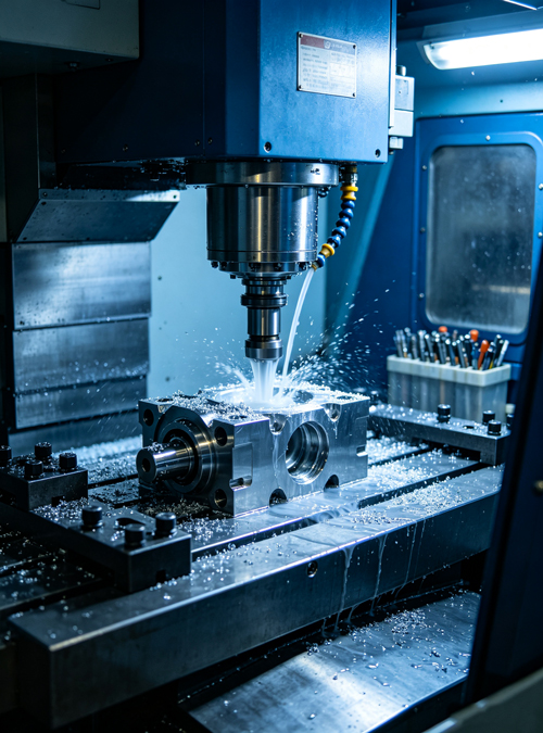
Single-setup five-axis machining
The sloped faces, deep cavity, curved transitions, and multi-angle holes were completed in one primary setup. The source record identifies stable position control to ±0.003 mm.
Staged roughing, aging, and finishing
Rough machining was followed by controlled aging, semi-finishing, a second low-temperature stabilization step, and final finishing.
Smooth contour milling
Five-axis interpolation eliminated visible handoff steps on curved surfaces and reduced stress concentration.
Dedicated fixtures and full inspection
Custom fixtures replaced four separate three-axis processes. CMM inspection covered contour and geometric tolerances.
A staged route designed for one-piece robot-joint stability.
Forging preparation
Verify the dense 7075-T6 forging and establish machining references.
Five-axis rough machining
Open the deep cavity and remove the primary material volume.
First stress-relief stage
Release the majority of machining stress before semi-finishing.
Semi-finishing and second stabilization
Refine the geometry and complete a second low-temperature stress-relief stage.
Five-axis finish machining
Complete the interfaces, holes, contours, and smooth curved transitions.
Deburring and hard anodizing
Finish deep edges and apply a wear- and corrosion-resistant surface.
100% CMM inspection
Verify profile, position, coaxiality, parallelism, and critical assembly features.
Full geometric inspection for a high-accuracy robotic assembly.
The source specifies critical tolerances to ±0.005 mm, with material verification, first-article CMM inspection, and 100% finished-part contour and geometric inspection.
Material grade, position, coaxiality, parallelism, curved-surface profile, dimensional stability after aging, anodized surface, and batch traceability.
Higher load capacity with lower rework and shorter machining time.
The supplied case record reports that the robot operated without binding or vibration and that the smooth one-piece structure supported improved fatigue performance.
Prototype lead time was reduced to 18 days, unit cost reportedly declined by 18%, and batch yield reached 99.8%.
Quantitative, certification, qualification, and environmental-test outcomes are based on the supplied project documentation and should be verified against internal records before public publication.
Approved for annual production and joint development.
The customer reported eight months of full-load operation without structural damage. Following the initial batch, the companies entered an annual framework program for additional lightweight robot-joint components.
Project outcome summary based on the supplied case record